Layouts
Overview
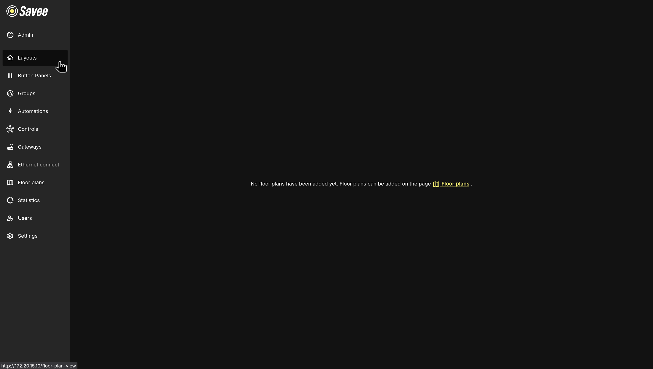
The Layouts page provides a visual map-based representation of your Savee device network. Devices are placed on floor plans or geographic maps, allowing you to monitor their status and control them directly from the interface without needing to navigate through lists.
If no floor plans have been configured yet, the page will display a + Add floor plan button near the top edge of the page.
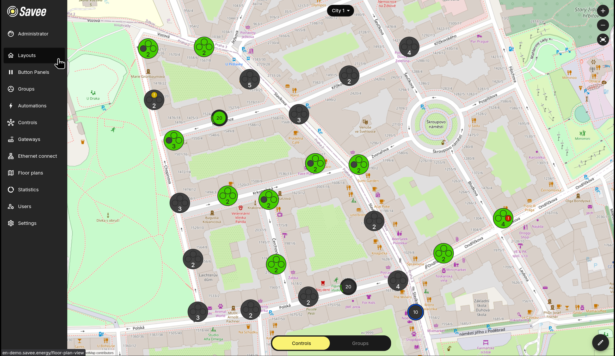
Once floor plans are added, the layout displays device icons positioned on the map. You can interact with devices directly from this view.
Navigation and Controls
The following controls are available on the Layouts page:
| Control | Location | Description |
|---|---|---|
| Floor plan selector | Top center | Switch between available floor plans or maps. |
| Zoom in / Zoom out | Top right | Adjust the map zoom level. |
| Fullscreen | Top right | Expand the layout to fill the entire screen. |
| Display Settings | Bottom left (upper) | Set filters and configure display settings. |
| Controls / Groups toggle | Bottom left (lower) | Switch between individual device control and group control mode. |
| Edit (pencil icon) | Bottom right | Show options to add, move, or delete devices and groups on the layout or edit the current floor plan. |
Device Icon Colors
Device icons change color to reflect their current state at a glance.
Actuators
| Color | Meaning |
|---|---|
| Green | Device is on. |
| Gray | Device is off. |
| Yellow | Device's gateway is in service mode. |
| Red | Device is unreachable. |
| Blue ring | Device is currently in automation mode. |
Sensors
| Color | Meaning |
|---|---|
| Blue | Device is on and functioning normally. |
| Yellow | Device's gateway is in service mode. |
| Red | Device is unreachable. |
Controls Mode
In Controls mode (default), each device icon on the map represents a single device. Clicking an icon allows you to toggle it on or off, holding and dragging adjusts its output level (if possible), or view its current readings depending on the device type.
Groups Mode
Switching to Groups mode at the bottom of the screen changes the view to show device groups instead of individual devices. Group icons display the state of the group and allow direct control of device groups. This is useful for managing large areas or sections of a building efficiently.
Editing the Layout
To modify the arrangement of devices or groups on the layout, click the pencil icon in the bottom-right corner of the screen. Here you can:
- Add devices or groups by selecting them from the panel and placing them on the map.
- Move existing icons by dragging them to a new position.
- Delete devices or groups by selecting an icon and choosing the delete option.
- Edit Floor Plan if you need to edit the floor plan used as the layout's background.
Note
Device positions on map layouts are synchronized with the Location column in the Controls table. Moving a device on the map updates its GPS location in Controls, and editing the location in Controls updates the device's position on the map.
Display Settings
Click the Display Settings button in the bottom-left corner of the Layouts page to filter controls or groups on the current floor plan, display labels, enable clustering, etc.
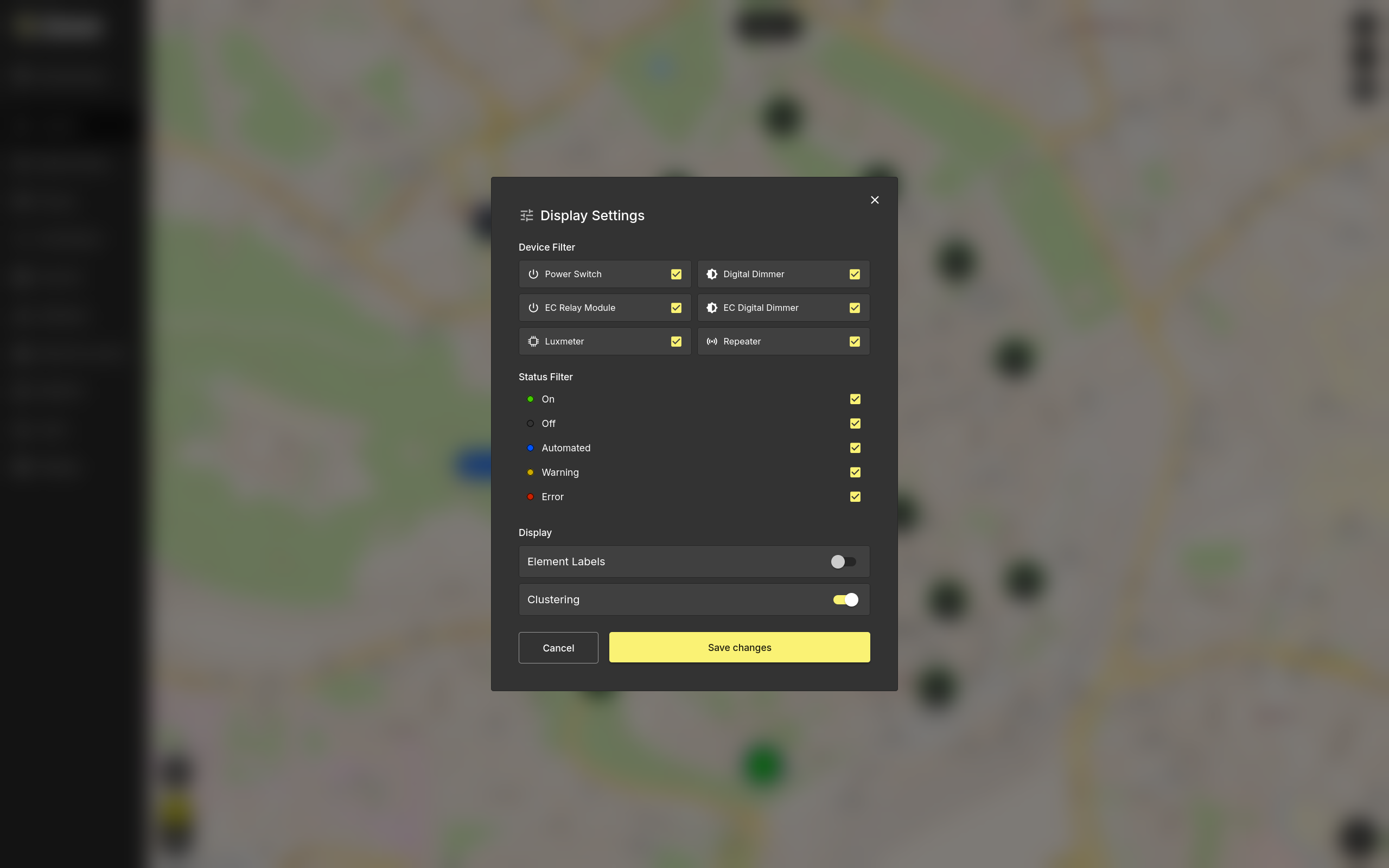
The display settings are split into several sections:
- Device Filter lets you show or hide specific device types, such as power switches, relay modules, dimmers, luxmeters, and repeaters.
- Status Filter lets you show or hide devices by their current status: On, Off, Automated, Warning, or Error.
- Control Labels controls whether device and group labels are displayed on the layout.
- Clustering groups nearby controls together when the layout is zoomed out, making dense floor plans easier to read.
Click Save changes to apply the selected display settings, or Cancel to close the dialog without saving.
Managing Floor Plans
Floor plans are managed directly from the Layouts page. They provide the background canvas for the layout, either as an uploaded image or as an interactive geographic map. Devices and groups are then placed on top of the selected floor plan for visual control and monitoring.
If no floor plans have been configured yet, click + Add floor plan on the empty Layouts page. If floor plans already exist, use the Floor plan selector at the top of the page to switch between them, then click the pencil icon in the bottom-right corner and choose Edit Floor Plan to manage the selected floor plan.
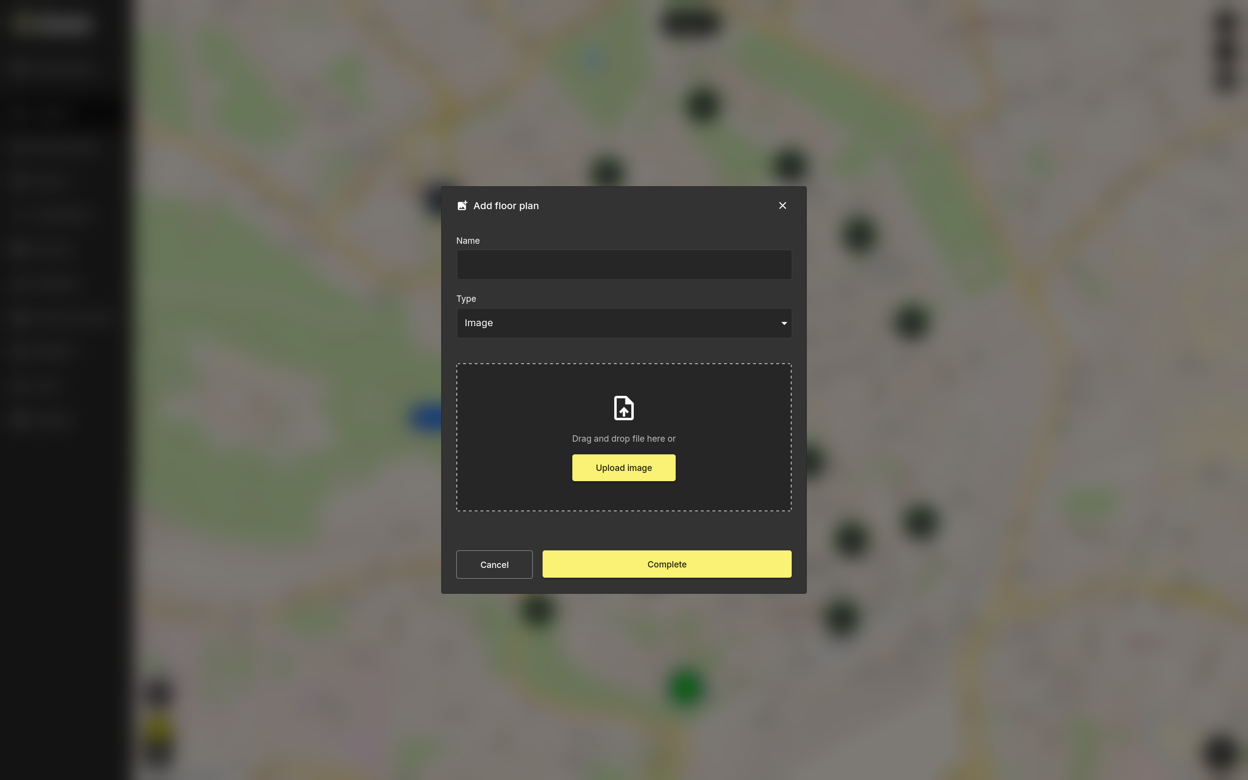
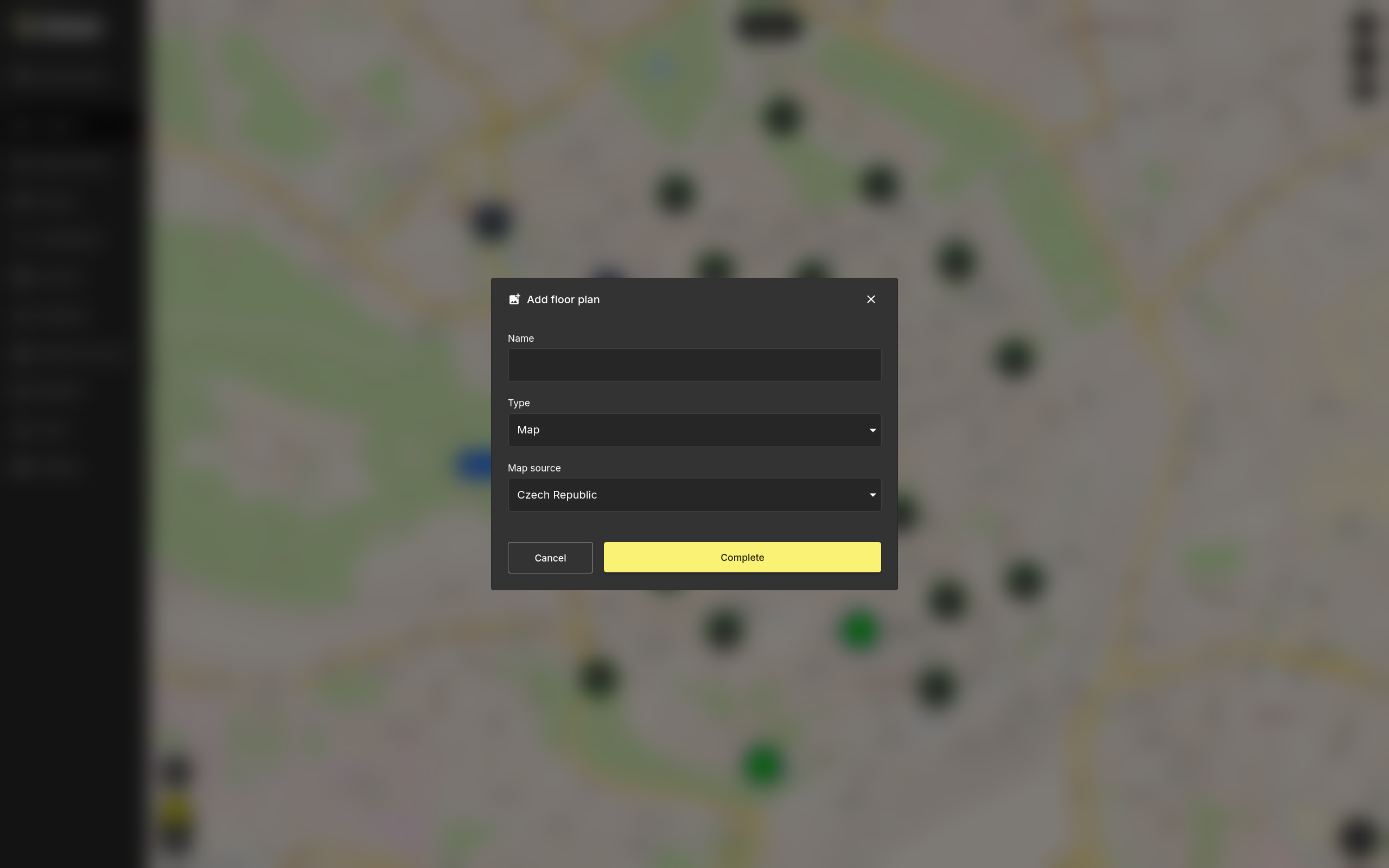
Adding a Floor Plan
When adding a floor plan, enter a unique Name and choose the Type of background to use.
Type: Image
Upload a custom floor plan image by dragging and dropping a file onto the upload area or clicking Upload image. Supported formats are .png and .jpg.
Type: Map
Use an interactive geographic map (OpenStreetMap) as the layout background. No file upload is required.
Click Complete to save the floor plan. It will then become available in the Floor plan selector.
Editing or Deleting a Floor Plan
Use the Edit Floor Plan button under the pencil icon to rename the selected floor plan, change its type, or replace the uploaded image with a new one.
Deleting a floor plan permanently removes it from Layouts. This action cannot be undone.
Tip
The default layout view can be customized per user by an administrator. Navigate to Users, select the desired user, and adjust the preferred floor plan under the Default view setting.