Gateways
Overview
The Gateways page manages the gateways that make up the Savee wireless network. Each gateway acts as a communication hub, connecting and coordinating the devices in its radio range.
The page uses the same split-panel layout as Groups and Automations: the gateway list is on the left and the gateway detail view is on the right.
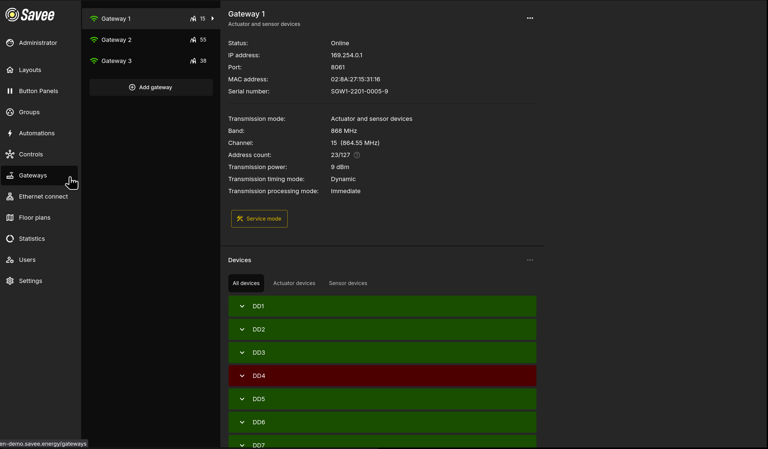
Each gateway in the list shows its name, a signal icon, and the number of paired device addresses. Click a gateway to open its detail view.
To add a new gateway, click + Add gateway at the bottom of the list.
Gateway Detail View
The detail view shows the full configuration and status of the selected gateway. Use the ⋯ menu in the top-right to edit gateway settings (see Managing Gateways).
| Property | Description |
|---|---|
| Status | Current connectivity status (e.g. Online). |
| IP address | The network address used to reach the gateway. |
| Port | The port used for communication with the gateway. |
| MAC address | The hardware address of the gateway. |
| Serial number | The gateway's unique serial number. |
| Transmission mode | The type of devices the gateway communicates with (e.g. Actuator and sensor devices). |
| Band | The radio frequency band used (e.g. 868 MHz). |
| Channel | The specific channel and its frequency in use. |
| Address count | How many device addresses are currently in use out of the maximum available. |
| Transmission power | The radio transmit power in dBm. |
| Transmission timing mode | Dynamic — adjusts time slot size based on the number of connected devices, optimizing speed. Static — fixed time slots, slower but more stable under high interference. |
| Transmission processing mode | Immediate — commands execute as soon as they are transmitted, suitable for smaller environments. Sequential — commands execute on device re-request, reducing peak power load in larger spaces. Simultaneous — commands wait until all devices receive the signal, ensuring synchronized actions. |
Service Mode
The Service mode button below the gateway properties unlocks advanced tools for network management and device pairing. The following features become available in service mode:
| Feature | Description |
|---|---|
| Build Network | After devices are placed in their final positions, triggers Savee to calculate the optimal communication routes between all devices. |
| HW Diagnostics | Displays detailed hardware information such as CPU voltage, CPU temperature, and serial number. |
| Network Topology | Shows an interactive map of the network, making it easier to understand device connections and troubleshoot communication paths. |
| Device Pairing and Settings | Enables pairing of new devices with the gateway and access to device-specific settings. |
Warning
Several options in the ⋯ menu (such as editing network configuration and communication settings) are only accessible while service mode is active.
Managing Gateways
The ⋯ menu in the gateway detail view provides the following options:
| Option | Description |
|---|---|
| Edit Device Information | Change the gateway's name and description. |
| Edit Network Configuration | Update the IP address, port, or identity key the application uses to reach the gateway. |
| Edit Communication Settings | Modify the channel, transmission power, gateway type, timing mode, or processing mode. |
| Replace Gateway | Connect a new physical gateway that takes over the identity of the current one. Useful after a hardware failure. |
| Remove Gateway | Permanently removes the gateway from Savee. |
Adding a Gateway
Clicking + Add gateway opens a multi-step setup wizard:
Step 1 — Basic Information
| Field | Description |
|---|---|
| Gateway name | A descriptive name to identify the gateway in the list. |
| Description | An optional description such as the gateway's location or purpose. |
Step 2 — Network Configuration
| Field | Description |
|---|---|
| IP address | The network address of the gateway. |
| Port | The port number used for data transmission. |
| Gateway key | The unique key used for secure communication. |
Alternatively, upload a .json configuration file exported from the gateway's configuration software to fill these fields automatically.
Step 3 — Communication Settings
| Field | Description |
|---|---|
| Communication channel | The frequency channel the gateway will use. |
| Transmission power | The signal strength and coverage level. |
| Gateway type | The gateway's primary role in the network. |
| Timing mode | Dynamic or Static (see detail view properties above). |
| Processing mode | Immediate, Sequential, or Simultaneous (see detail view properties above). |
Tip
Fine-tune communication settings to match the installation environment for optimal stability. For technical specifications and wiring examples, refer to the gateway hardware documentation.
Devices
Below the gateway properties, the Devices section lists all devices paired to the selected gateway. The list is split into three tabs:
| Tab | Shows |
|---|---|
| All devices | Every device paired to this gateway. |
| Actuator devices | Output devices only (e.g. dimmers, relays). |
| Sensor devices | Input devices only (e.g. lux meters, input modules). |
Each device row is expandable — click the chevron to view and manage the individual channels or sub-devices it contains.
Pairing a New Device
To pair a new device to a gateway, enter Service mode and click + Add devices:
- Select the device type, enter a name, and optionally add a description.
- Enable Bulk Pairing if you need to pair multiple devices sequentially — each device will automatically receive a numbered suffix.
- Click Pair to start a 10-second countdown. Press the physical pairing button on the device within this window to complete pairing.
Note
Zhaga devices use a magnetic contact instead of a physical button for pairing, which allows pairing while the device is inside its plastic dome.